


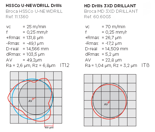
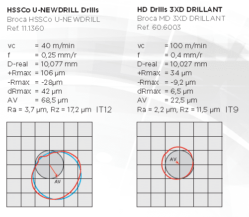
Over 60 years in the manufacture and distribution of tools
high performance cutting for machining sector.
| TALADROS PREVIOS PARA ROSCADO / PREVIOUS DRILLING FOR THREADING | ||||||||||||||||||||
| ISO M | Paso mm | Broca Ø | ISO M | Paso mm | Broca Ø | ISO MF | Paso mm | Broca Ø | ISO MF | Paso mm | Broca Ø | ISO MF | Paso mm | Broca Ø | ||||||
| 1.6 | 0,35 | 1,25 | 16 | 2,0 | 14,0 | 4,5 | 0,50 | 4,0 | 15 | 1,00 | 14,0 | 25 | 2,00 | 23,0 | ||||||
| 1.7 | 0,35 | 1,30 | 18 | 2,5 | 15,5 | 5,0 | 0,50 | 4,5 | 15 | 1,50 | 13,5 | 27 | 1,00 | 26,0 | ||||||
| 1.8 | 0,35 | 1,45 | 20 | 2,5 | 17,5 | 5,5 | 0,50 | 5,0 | 16 | 1,00 | 15,0 | 27 | 1,50 | 25,5 | ||||||
| 2,0 | 0,40 | 1,60 | 22 | 2,5 | 19,5 | 6,0 | 0,75 | 5,2 | 16 | 1,50 | 14,5 | 27 | 2,00 | 25,0 | ||||||
| 2.2 | 0,45 | 1,75 | 24 | 3,0 | 21,0 | 7,0 | 0,75 | 6,2 | 17 | 1,00 | 16,0 | 28 | 1,00 | 27,0 | ||||||
| 2.3 | 0,40 | 1,90 | 27 | 3,0 | 24,0 | 8,0 | 0,75 | 7,2 | 17 | 1,50 | 15,5 | 28 | 1,50 | 26,5 | ||||||
| 2.5 | 0,45 | 2,05 | 30 | 3,5 | 26,5 | 8,0 | 1,00 | 7,0 | 18 | 1,00 | 17,0 | 28 | 2,00 | 26,0 | ||||||
| 2.6 | 0,45 | 2,10 | 33 | 3,5 | 29,5 | 9,0 | 0,75 | 8,2 | 18 | 1,50 | 16,5 | 30 | 1,00 | 29,0 | ||||||
| 3,0 | 0,50 | 2,50 | 36 | 4,0 | 32,0 | 9,0 | 1,00 | 8,0 | 18 | 2,00 | 16,0 | 30 | 1,50 | 28,5 | ||||||
| 3.5 | 0,60 | 2,90 | 39 | 4,0 | 35,0 | 10 | 0,75 | 9,2 | 20 | 1,00 | 19,0 | 30 | 2,00 | 28,0 | ||||||
| 4,0 | 0,70 | 3,30 | 42 | 4,5 | 37,5 | 10 | 1,00 | 9,0 | 20 | 1,50 | 18,5 | 30 | 3,00 | 27,0 | ||||||
| 4.5 | 0,75 | 3,75 | 45 | 4,5 | 40,5 | 10 | 1,25 | 8,8 | 20 | 2,00 | 18,0 | 32 | 1,50 | 30,5 | ||||||
| 5,0 | 0,80 | 4,20 | 11 | 0,75 | 10,2 | 22 | 1,00 | 21,0 | 32 | 2,00 | 30,0 | |||||||||
| 6,0 | 1,00 | 5,00 | 11 | 1,00 | 10,0 | 22 | 1,50 | 20,5 | 33 | 1,50 | 31,5 | |||||||||
| 7,0 | 1,00 | 6,00 | ISO MF | Paso mm | Broca Ø | 12 | 1,00 | 11,0 | 22 | 2,00 | 20,0 | 33 | 2,00 | 31,0 | ||||||
| 8,0 | 1,25 | 6,80 | 12 | 1,25 | 10,8 | 24 | 1,00 | 23,0 | 33 | 3,00 | 30,0 | |||||||||
| 9,0 | 1,25 | 7,80 | 2,5 | 0,35 | 2,2 | 12 | 1,50 | 10,5 | 24 | 1,50 | 22,5 | 35 | 1,50 | 33,5 | ||||||
| 10 | 1,50 | 8,50 | 3,0 | 0,35 | 2,65 | 14 | 1,00 | 13,0 | 24 | 2,00 | 22,0 | 36 | 1,50 | 34,5 | ||||||
| 12 | 1,75 | 10,20 | 3,5 | 0,35 | 3,15 | 14 | 1,25 | 12,8 | 25 | 1,00 | 24,0 | 36 | 2,00 | 34,0 | ||||||
| 14 | 2,00 | 12,00 | 4,0 | 0,50 | 3,5 | 14 | 1,50 | 12,5 | 25 | 1,50 | 23,5 | 36 | 3,00 | 33,0 | ||||||
| UNC | Paso mm | Broca Ø | UNF | Paso mm | Broca Ø | GAS | Paso mm | Broca Ø | W BSW | Paso mm | Broca Ø | |||||||||
| 2 | 56 | 1,80 | 2 | 64 | 1,80 | 1/8" | 28 | 8,70 | 1/8" | 40 | 2,50 | |||||||||
| 3 | 48 | 2,00 | 3 | 56 | 2,10 | 1/4" | 19 | 11,60 | 3/16" | 24 | 3,60 | |||||||||
| 4 | 40 | 2,30 | 4 | 48 | 2,40 | 3/8" | 19 | 15,25 | 1/4" | 20 | 5,10 | |||||||||
| 5 | 40 | 2,60 | 5 | 44 | 2,60 | 1/2" | 14 | 19,00 | 5/16" | 18 | 6,50 | |||||||||
| 6 | 32 | 2,70 | 6 | 40 | 2,90 | 5/8" | 14 | 20,75 | 3/8" | 16 | 7,90 | |||||||||
| 8 | 32 | 3,50 | 8 | 36 | 3,50 | 3/4" | 14 | 24,25 | 7/16" | 14 | 9,20 | |||||||||
| 10 | 24 | 3,80 | 10 | 32 | 4,00 | 7/8" | 14 | 28,25 | 1/2" | 12 | 10,50 | |||||||||
| 12 | 24 | 4,50 | 12 | 28 | 4,60 | 1" | 11 | 30,50 | 5/8" | 11 | 13,50 | |||||||||
| 1/4" | 20 | 5,10 | 1/4" | 28 | 5,40 | 1 · 1/8" | 11 | 35,50 | 3/4" | 10 | 16,25 | |||||||||
| 5/16" | 18 | 6,50 | 5/16" | 24 | 6,90 | 1 · 1/2" | 11 | 45,00 | 7/8" | 9 | 19,25 | |||||||||
| 3/8" | 16 | 7,90 | 3/8" | 24 | 8,40 | 1 · 3/4" | 11 | 51,00 | 1" | 8 | 22,00 | |||||||||
| 7/16" | 14 | 9,30 | 7/16" | 20 | 9,90 | 2" | 11 | 57,00 | 1 · 1/8" | 7 | 24,50 | |||||||||
| 1/2" | 13 | 10,70 | 1/2" | 20 | 11,50 | 2 · 1/4" | 11 | 63,00 | 1 · 1/4" | 7 | 27,75 | |||||||||
| 9/16" | 12 | 12,30 | 9/16" | 18 | 13,00 | 2 · 1/2" | 11 | 72,50 | 1 · 3/8" | 6 | 30,50 | |||||||||
| 5/8" | 11 | 13,50 | 5/8" | 18 | 14,50 | 2 · 3/4" | 11 | 79,00 | 1 · 1/2" | 6 | 33,50 | |||||||||
| 3/4" | 10 | 16,50 | 3/4" | 16 | 17,40 | 3" | 11 | 85,50 | 1 · 5/8" | 5 | 35,50 | |||||||||
| 7/8" | 9 | 19,30 | 7/8" | 14 | 20,40 | 3 · 1/4" | 11 | 91,50 | 1 · 3/4" | 5 | 38,50 | |||||||||
| 1" | 8 | 22,25 | 1" | 12 | 23,25 | 3 · 1/2" | 11 | 91,75 | 1 · 7/8" | 4,5 | 41,25 | |||||||||
| PREVIOUS DRILLING FOR REAMING - TALADRADO PREVIO PARA ESCARIADO | |||||
| Material | Ø up to 6 mm Ø hasta 6 mm |
Ø up to 10 mm Ø hasta 10 mm |
Ø up to 16 mm Ø hasta 16 mm |
Ø up to 25 mm Ø hasta 25 mm |
Ø over 25 mm Ø desde 25 mm |
| Steels up to 700 N/mm2 Aceros hasta 700 N/mm2 |
0,1 - 0,2 | 0.2 | 0,2 - 0,3 | 0,3 - 0,4 | 0.4 |
| Steels 700 - 1000 N/mm2 Aceros 700 - 1000 N/mm2 |
0,1 - 0,2 | 0.2 | 0.2 | 0.3 | 0,3 - 0,4 |
| Cast steel Acero fundido |
0,1 - 0,2 | 0.2 | 0.2 | 0,2 - 0,3 | 0,3 - 0,4 |
| Cast iron GG Fundición GG |
0,1 - 0,2 | 0.2 | 0,2 - 0,3 | 0,3 - 0,4 | 0,3 - 0,4 |
| Cast iron GGG Fundición GGG |
0,1 - 0,2 | 0.2 | 0.3 | 0,3 - 0,4 | 0.4 |
| Copper Cobre |
0,1 - 0,2 | 0,2 - 0,3 | 0,3 - 0,4 | 0.4 | 0,4 - 0,5 |
| Brass - Bronze Latón - Bronce |
0,1 - 0,2 | 0.2 | 0,2 - 0,3 | 0.3 | 0,3 - 0,4 |
| Light alloys Aleaciones ligeras |
0,1 - 0,2 | 0,2 - 0,3 | 0,3 - 0,4 | 0.4 | 0,4 - 0,5 |
| Plastics, hard Duroplásticos |
0,1 - 0,2 | 0.2 | 0.4 | 0,4 - 0,5 | 0.5 |
| Plastics, soft Termoplásticos |
0,1 - 0,2 | 0.2 | 0.2 | 0.3 | 0,3 - 0,4 |
| Stock allowance (recommended values in mm) · Masa a escariar (valores recomendados en mm) Due to the efficient action of the spiral, the values for quick spiral reamers may be increased by 50 to 100%. Los valores para los escariadores de gran rendimiento pueden aumentarse de un 50 a un 100%. |
|||||
| HB | HV | Rockwell ** | HS | Approx. tensile strength (MPa)* | HB | HV | Rockwell ** | HS | Approx. tensile strength (MPa)* | |||||||||
| Brinell, 10mm ball, Load 3000kg Brinell, bola 10mm, carga 3000k |
Vickers | Shore | Brinell, 10mm ball, Load 3000kg Brinell, bola 10mm, carga 3000k |
Vickers | Shore | |||||||||||||
| HRA | HRB | HRC | HRD | HRA | HRB | HRC | HRD | |||||||||||
| Standard ball Bola estándar |
Tungsten carbide ball Bola de carburo al tungsteno |
A | B | C | D | Standard ball Bola estándar |
Tungsten carbide ball Bola de carburo al tungsteno |
A | B | C | D | |||||||
| Aprox. tracción fuerza (MPa)* | Aprox. tracción fuerza (MPa)* | |||||||||||||||||
| − | − | 940 | 85.6 | − | 68.0 | 76.9 | 97 | − | 429 | 429 | 455 | 73.4 | − | 45.7 | 59.7 | 61 | 1510 | |
| − | − | 920 | 85.3 | − | 67.5 | 76.5 | 96 | − | 415 | 415 | 440 | 72.8 | − | 44.5 | 58.8 | 59 | 1460 | |
| − | − | 900 | 85.0 | − | 67.0 | 76.1 | 95 | − | 401 | 401 | 425 | 72.0 | − | 43.1 | 57.8 | 58 | 1390 | |
| − | (767) | 880 | 84.7 | − | 66.4 | 75.7 | 93 | − | 388 | 388 | 410 | 71.4 | − | 41.8 | 56.8 | 56 | 1330 | |
| − | (757) | 860 | 84.4 | − | 65.9 | 75.3 | 92 | − | 375 | 375 | 396 | 70.6 | − | 40.4 | 55.7 | 54 | 1270 | |
| − | (745) | 840 | 84.1 | − | 65.3 | 74.8 | 91 | − | 363 | 363 | 383 | 70.0 | − | 39.1 | 54.6 | 52 | 1220 | |
| − | (733) | 820 | 83.8 | − | 64.7 | 74.3 | 90 | − | 352 | 352 | 372 | 69.3 | (110.0) | 37.9 | 53.8 | 51 | 1180 | |
| − | (722) | 800 | 83.4 | − | 64.0 | 73.8 | 88 | − | 341 | 341 | 360 | 68.7 | (109.0) | 36.6 | 52.8 | 50 | 1130 | |
| − | (712) | − | − | − | − | − | − | − | 331 | 331 | 350 | 68.1 | (108.5) | 35.5 | 51.9 | 48 | 1095 | |
| − | (710) | 780 | 83.0 | − | 63.3 | 73.3 | 87 | − | 321 | 321 | 339 | 67.5 | (108.0) | 34.3 | 51.0 | 47 | 1060 | |
| − | (698) | 760 | 82.6 | − | 62.5 | 72.6 | 86 | − | 311 | 311 | 328 | 66.9 | (107.5) | 33.1 | 50.0 | 46 | 1025 | |
| − | (684) | 740 | 82.2 | − | 61.8 | 72.1 | − | − | 302 | 302 | 319 | 66.3 | (107.0) | 32.1 | 49.3 | 45 | 1005 | |
| − | (682) | 737 | 82.2 | − | 61.7 | 72.0 | 84 | − | 293 | 293 | 309 | 65.7 | (106.0) | 30.9 | 48.3 | 43 | 970 | |
| − | (670) | 720 | 81.8 | − | 61.0 | 71.5 | 83 | − | 285 | 285 | 301 | 65.3 | (105.5) | 29.9 | 47.6 | − | 950 | |
| − | (656) | 700 | 81.3 | − | 60.1 | 70.8 | − | − | 277 | 277 | 292 | 64.6 | (104.5) | 28.8 | 46.7 | 41 | 925 | |
| − | (653) | 697 | 81.2 | − | 60.0 | 70.7 | 81 | − | 269 | 269 | 284 | 64.1 | (104.0) | 27.6 | 45.9 | 40 | 895 | |
| − | (647) | 690 | 81.1 | − | 59.7 | 70.5 | − | − | 262 | 262 | 276 | 63.6 | (103.0) | 26.6 | 45.0 | 39 | 875 | |
| − | (638) | 680 | 80.8 | − | 59.2 | 70.1 | 80 | − | 255 | 255 | 269 | 63.0 | (102.0) | 25.4 | 44.2 | 38 | 850 | |
| − | 630 | 670 | 80.6 | − | 58.8 | 69.8 | − | − | 248 | 248 | 261 | 62.5 | (101.0) | 24.2 | 43.2 | 37 | 825 | |
| − | 627 | 667 | 80.5 | − | 58.7 | 69.7 | 79 | − | 241 | 241 | 253 | 61.8 | 100.0 | 22.8 | 42.0 | 36 | 800 | |
| − | − | 677 | 80.7 | − | 59.1 | 70.0 | − | − | 235 | 235 | 247 | 61.4 | 99.0 | 21.7 | 41.4 | 35 | 785 | |
| − | 601 | 640 | 79.8 | − | 57.3 | 68.7 | 77 | − | 229 | 229 | 241 | 60.8 | 98.2 | 20.5 | 40.5 | 34 | 765 | |
| − | − | 640 | 79.8 | − | 57.3 | 68.7 | − | − | 223 | 223 | 234 | − | 97.3 | (18.8) | − | − | − | |
| − | 578 | 615 | 79.1 | − | 56.0 | 67.7 | 75 | − | 217 | 217 | 228 | − | 96.4 | (17.5) | − | 33 | 725 | |
| − | − | 607 | 78.8 | − | 55.6 | 67.4 | − | − | 212 | 212 | 222 | − | 95.5 | (16.0) | − | − | 705 | |
| − | 555 | 591 | 78.4 | − | 54.7 | 66.7 | 73 | 2055 | 207 | 207 | 218 | − | 94.6 | (15.2) | − | 32 | 690 | |
| − | − | 579 | 78.0 | − | 54.0 | 66.1 | − | 2015 | 201 | 201 | 212 | − | 93.8 | (13.8) | − | 31 | 675 | |
| − | 534 | 569 | 77.8 | − | 53.5 | 65.8 | 71 | 1985 | 197 | 197 | 207 | − | 92.8 | (12.7) | − | 30 | 655 | |
| − | − | 553 | 77.1 | − | 52.5 | 65.0 | − | 1915 | 192 | 192 | 202 | − | 91.9 | (11.5) | − | 29 | 640 | |
| − | 514 | 547 | 76.9 | − | 52.1 | 64.7 | 70 | 1890 | 187 | 187 | 196 | − | 90.7 | (10.0) | − | − | 620 | |
| (495) | − | 539 | 76.7 | − | 51.6 | 64.3 | − | 1855 | 183 | 183 | 192 | − | 90.0 | (9.0) | − | 28 | 615 | |
| − | − | 530 | 76.4 | − | 51.1 | 63.9 | − | 1825 | 179 | 179 | 188 | − | 89.0 | (8.0) | − | 27 | 600 | |
| − | 495 | 528 | 76.3 | − | 51.0 | 63.8 | 68 | 1820 | 174 | 174 | 182 | − | 87.8 | (6.4) | − | − | 585 | |
| (477) | − | 516 | 75.9 | − | 50.3 | 63.2 | − | 1780 | 170 | 170 | 178 | − | 86.8 | (5.4) | − | 26 | 570 | |
| − | − | 508 | 75.6 | − | 49.6 | 62.7 | − | 1740 | 167 | 167 | 175 | − | 86.0 | (4.4) | − | − | 560 | |
| − | 477 | 508 | 75.6 | − | 49.6 | 62.7 | 66 | 1740 | 163 | 163 | 171 | − | 85.0 | (3.3) | − | 25 | 545 | |
| (461) | − | 495 | 75.1 | − | 48.8 | 61.9 | − | 1680 | 156 | 156 | 163 | − | 82.9 | (0.9) | − | − | 525 | |
| − | − | 491 | 74.9 | − | 48.5 | 61.7 | − | 1670 | 149 | 149 | 156 | − | 80.8 | − | − | 23 | 505 | |
| − | 461 | 491 | 74.9 | − | 48.5 | 61.7 | 65 | 1670 | 143 | 143 | 150 | − | 78.7 | − | − | 22 | 490 | |
| 444 | − | 474 | 74.3 | − | 47.2 | 61.0 | − | 1595 | 137 | 137 | 143 | − | 76.4 | − | − | 21 | 460 | |
| − | − | 472 | 74.2 | − | 47.1 | 60.8 | − | 1585 | 131 | 131 | 137 | − | 74.0 | − | − | − | 450 | |
| − | 444 | 472 | 74.2 | − | 47.1 | 60.8 | 63 | 1585 | 126 | 126 | 132 | − | 72.0 | − | − | 20 | 435 | |
| 121 | 121 | 127 | − | 69.8 | − | − | 19 | 415 | ||||||||||
| 116 | 116 | 122 | − | 67.6 | − | − | 18 | 400 | ||||||||||
| 111 | 111 | 117 | − | 65.7 | − | − | 15 | 385 | ||||||||||
| * 1 MPa = 1 N/mm2 ** Figures in ( ) are not commonly used. It’s just reference. Las figuras de ( ) no suelen emplearse. Se usan solo como referencia. |
A: Scale, Load 60kg, Brale Diamond · Escala, Carga 60kg, Diamante Brale B: Scale, Load 100kg, Diameter 1·16 in. Steel ball · Escala, Carga 100kg, Diámetro 1·16 in. Bola de acero C: Scale, Load 150kg, brale diamond · Escala, Carga 150kg, Diamante Brale D: Scale, Load 100kg, Brale Diamond · Escala, Carga 100kg, Diamante Brale |
|||||||||||||||||
| Basic size step Paso Básico tamaño (mm) |
Tolerance zone class of shaft · Zona de tolerancia clase de eje (µm) | |||||||||||||||||
| > | ≤ | e9 | f6 | f7 | f8 | g5 | g6 | h5 | h6 | h7 | h8 | h9 | js5 | js6 | js7 | k5 | k6 | |
| - | 3 | −14 −39 |
−6 −12 |
−6 −16 |
−6 −20 |
−2 −6 |
−2 −8 |
0 −4 |
0 −6 |
0 −10 |
0 −14 |
0 −25 |
±2 | ±3 | ±5 | +4 0 |
+6 0 |
|
| 3 | 6 | −20 −50 |
−10 −18 |
−10 −22 |
−10 −28 |
−4 −9 |
−4 −12 |
0 −5 |
0 −8 |
0 −12 |
0 −18 |
0 −30 |
±2.5 | ±4 | ±6 | +6 +1 |
+9 +1 |
|
| 6 | 10 | −25 −61 |
−13 −22 |
−13 −28 |
−13 −35 |
−5 −11 |
−5 −14 |
0 −6 |
0 −9 |
0 −15 |
0 −22 |
0 −36 |
±3 | ±4.5 | ±7 | +7 +1 |
+10 +1 |
|
| 10 | 14 | −32 −75 |
−16 −27 |
−16 −34 |
−16 −43 |
−6 −14 |
−6 −17 |
0 −8 |
0 −11 |
0 −18 |
0 −27 |
0 −43 |
±4 | ±5.5 | ±9 | +9 +1 |
+12 +1 |
|
| 14 | 18 | |||||||||||||||||
| 18 | 24 | −40 −92 |
−20 −33 |
−20 −41 |
−20 −53 |
−7 −16 |
−7 −20 |
0 −9 |
0 −13 |
0 −21 |
0 −33 |
0 −52 |
±4.5 | ±6.5 | ±10 | +11 +2 |
+15 +2 |
|
| 24 | 30 | |||||||||||||||||
| 30 | 40 | −50 −112 |
−25 −41 |
−25 −50 |
−25 −64 |
−9 −20 |
−9 −25 |
0 −11 |
0 −16 |
0 −25 |
0 −39 |
0 −62 |
±5.5 | ±8 | ±12 | +13 +2 |
+18 +2 |
|
| 40 | 50 | |||||||||||||||||
| 50 | 65 | −60 −134 |
−30 −49 |
−30 −60 |
−30 −76 |
−10 −23 |
−10 −29 |
0 −13 |
0 −19 |
0 −30 |
0 −46 |
0 −74 |
±6.5 | ±9.5 | ±15 | +15 +2 |
+21 +2 |
|
| 65 | 80 | |||||||||||||||||
| 80 | 100 | −72 −159 |
−36 −58 |
−36 −71 |
−36 −90 |
−12 −27 |
−12 −34 |
0 −15 |
0 −22 |
0 −35 |
0 −54 |
0 −87 |
±7.5 | ±11 | ±17 | +18 +3 |
+25 +3 |
|
| 100 | 120 | |||||||||||||||||
| Basic size step Paso Básico tamaño (mm) |
Tolerance zone class of hole · Zona de tolerancia clase de agujero (µm) | |||||||||||||||||
| > | ≤ | E7 | E8 | E9 | F6 | F7 | F8 | G6 | G7 | H6 | H7 | H8 | H9 | H10 | JS6 | JS7 | K6 | K7 |
| - | 3 | +24 +14 |
+28 +14 |
+39 +14 |
+12 +6 |
+16 +6 |
+20 +6 |
+8 +2 |
+12 +2 |
+6 0 |
+10 0 |
+14 0 |
+25 0 |
+40 0 |
±3 | ±5 | 0 −6 |
0 −10 |
| 3 | 6 | +32 +20 |
+38 +20 |
+50 +20 |
+18 +10 |
+22 +10 |
+28 +10 |
+12 +4 |
+16 +4 |
+8 0 |
+12 0 |
+18 0 |
+30 0 |
+48 0 |
±4 | ±6 | +2 −6 |
+3 −9 |
| 6 | 10 | +40 +25 |
+47 +25 |
+61 +25 |
+22 +13 |
+28 +13 |
+35 +13 |
+14 +5 |
+20 +5 |
+9 0 |
+15 0 |
+22 0 |
+36 0 |
+58 0 |
±4.5 | ±7 | +2 −7 |
+5 −10 |
| 10 | 14 | +50 +32 |
+59 +32 |
+75 +32 |
+27 +16 |
+34 +16 |
+43 +16 |
+17 +6 |
+24 +6 |
+11 0 |
+18 0 |
+27 0 |
+43 0 |
+70 0 |
±5.5 | ±9 | +2 −9 |
+6 −12 |
| 14 | 18 | |||||||||||||||||
| 18 | 24 | +61 +40 |
+73 +40 |
+92 +40 |
+33 +20 |
+41 +20 |
+53 +20 |
+20 +7 |
+28 +7 |
+13 0 |
+21 0 |
+33 0 |
+52 0 |
+84 0 |
±6.5 | ±10 | +2 −11 |
+6 −15 |
| 24 | 30 | |||||||||||||||||
| 30 | 40 | +75 +50 |
+89 +50 |
+112 +50 |
+41 +25 |
+50 +25 |
+64 +25 |
+25 +9 |
+34 +9 |
+16 0 |
+25 0 |
+39 0 |
+62 0 |
+100 0 |
±8 | ±12 | +3 −13 |
+7 −18 |
| 40 | 50 | |||||||||||||||||
| 50 | 65 | +90 +60 |
+106 +60 |
+134 +60 |
+49 +30 |
+60 +30 |
+76 +30 |
+29 +10 |
+40 +10 |
+19 0 |
+30 0 |
+46 0 |
+74 0 |
+120 0 |
±9.5 | ±15 | +4 −15 |
+9 −21 |
| 65 | 80 | |||||||||||||||||
| 80 | 100 | +107 +72 |
+126 +72 |
+159 +72 |
+58 +36 |
+71 +36 |
+90 +36 |
+34 +12 |
+47 +12 |
+22 0 |
+35 0 |
+54 0 |
+87 0 |
+140 0 |
±11 | ±17 | +4 −18 |
+10 −25 |
| 100 | 120 | |||||||||||||||||
| In every step given in the table, the value on the upper side shows the upper deviation and the value on the lower side, the lower deviation. Para cada paso de la tabla, el valor del lado superior muestra la desviación del lado superior y el valor del lado inferior, la desviación inferior |
||||||||||||||||||
| COVENTRY TOOLS BITS | CARBIDE BRAZED TURNING TOOLS | |||||||
| Co 10% | SPEZIAL | ASP-60 | P-20 | P-40 | K-10 | M-10 | ||
| MATERIAL MANUFACTURING | High speed steel 10% Cobalt alloy. First choice quality. | High-speed steel cobalt alloy, Tungsten and Carbon | High alloy ASP-60 powder metallurgical grade with a more even distribution of cobalt, tungsten and Carbide particles.. | Premium carbide imported from Germany and under ISO. | ||||
| APPLICATIONS | Turning, grooving and parting off. General purpose cutting tools. | High feed turning. Means cutting depths. | High wear resistance cutting edge. Turning and parting off. | Turning, grooving, threading. Generalmachining. | Turning, grooving, high feed ordificult conditions. | Turning, grooving, threading. Generalmachining. | Turning, grooving, threading. Generalmachining. | |
| MACHINING | Tough materials Wood Extrusion Shearing tools |
Tough materials Wood Extrusion Shearing tools |
Carbon steel, stainless steel,aluminium alloys, heat resistant alloys. | First choice grade for general turning steel. | Steel machining under difficult conditions. | Aleaciones de cobre a alta temperatura. Universal grade for cast iron,aluminium, abrasive materials and copper alloys. |
Turning stainless steels and wear resistants manganese steels. | |
| RESISTANCE | Allowed in difficult cutting conditions. |
High wear resistance and machining withhigh concentration of heat. | Alta resistencia al desgaste. Alta resistencia de la arista de corte. High wear resistance. High strength cutting edge. |
High wear resistance. | Allowed in difficult cutting conditions. |
High wear resistance. | High wear resistance. | |
| REGRINDING | Regrinding easily with ceramic or CBN wheels. | Regrinding easily with ceramic or CBN wheels. | Regrinding easily with ceramic or CBN wheels. | Silicon carbide Wheel, finish withdiamond wheel. | ||||
| SPECIAL FEATURES | Good results in wide materials range. |
Better wear resistance at cutting edge. |
Increased productivity by higher cutting conditions and increased wear resistance. |
Optimal performance in machining processes | ||||